Oscillation Controller with Integrated Digital PLL
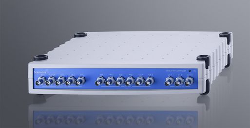
The Oscillation Controller (OC4) adds dynamic and multifrequency AFM capabilities to the Nanonis Mimea™ controller. With an input bandwidth of 5MHz, the OC4 can operate any type of cantilever, tuning fork, needle sensors, etc. and their harmonics. It is also perfect as a digital lock-in and signal analyzer (FFT) up to 5 MHz and can be further extended for Kelvin probe applications or customized in LabVIEW with the Nanonis Programming Interface.
Please head to the dedicated Oscillation Controller page for more details
Dual-OC4 for multi-excitation AFM
A second oscillation controller adds a second physical output and input pair. This is necessary, for example, when performing AM-KPFM measurements where the cantilever is excited electrostatically by applying a second modulation frequency to the sample (or tip). A second OC4 is also required for the TrueDissipation™ calibration.
The dual-OC4 hardware is identical to that of the OC4 add-on described above, but the package includes the Kelvin Module (see below) and the TrueDissipation functionality.
Please head to the dedicated Oscillation Controller page for more details
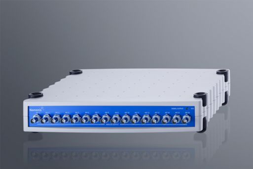
Additional Nanonis SC5 for more inputs and outputs
With growing set-up complexity, or when multiple stages need to be controlled, 8 input and output channels might simply not be enough. One additional SC5 instantaneously doubles that number to 16. For even more complex experiments, a maximum of 3 SC5s can be connected to the Nanonis Mimea™ SPM Control System base package, transforming the instrument into a 24 outputs and 24 inputs system.
While increasing the number of channels with conventional systems means adapting the measurement software and potentially changing the workflow, the modularity of the Nanonis Mimea™ SPM Control System avoids all these drawbacks. The additional SC5 signals are seamlessly integrated into the Nanonis software allowing immediate productivity
Additional SC5s can be combined with additional SO5s (16-output channels, see below) if more outputs than inputs are required. The following combinations are possible (sorted by increasing number of outputs):
| Configuration | Total number of outputs | Total number of inputs |
| BP5e | 8 | 8 |
| 1 SC5 add-on | 16 | 16 |
| 1 SO5 add-on | 24 | 8 |
| 2 SC5 add-ons | 24 | 24 |
| 1 SC5 and SO5 add-on | 32 | 16 |
| 2 SO5 add-ons | 40 | 8 |
| 2 SC5 and 1SO5 add-on | 40 | 24 |
| 1 SC5 and 2 SO5 add-on | 48 | 16 |
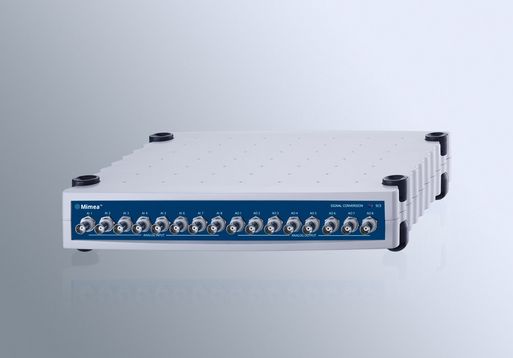
Nanonis SO5 for multiprobe systems
As SPM research evolves, the combination of multiple measurement techniques becomes more significant. This includes the ability to combine transport and SPM measurements, thus requiring an increased number of precision, low-noise voltage sources. At the same time multiple probes might be required to perform transport requirements, and that also requires multiple outputs to generate the X, Y, and Z voltages for the various probes. For such configurations, the number of required output channels grows much quicker compared to the required input channels, meaning that an additional SC5 with 8 input and 8 output channels might not provide enough output channels, and two SC5s might not be the most cost-effective solution.
The SO5 add-on is the ideal solution for such cases, as it provides 16 low-noise, low-drift, high precision outputs seamlessly integrated into the Nanonis software. The SO5 add-on can be combined with up to two SC5 add-ons, leading to a maxed-out configurations with 40 outputs and 24 inputs.
The SO5 analog outputs have identical specifications to the analog outputs of the SC5 (with the exception of the 22-bit hrDAC™ mode) meaning no compromise on signal quality. And while increasing the number of channels normally means integrating external instruments, adapting the measurement software and potentially changing the workflow, with the Nanonis Mimea™ SPM Control System none of this is necessary. The additional SO5 signals are seamlessly integrated into the Nanonis software allowing immediate productivity. All SO5 channels can be accessed by the lock-in and function generator modules.
Lock-in modules


The lockin amplifier modules let you modulate and demodulate any of the input and output signals available in the Nanonis controller with frequencies up to 40 kHz. Up to 8 lockin detector modules can be used independently from each other or synchronized in a phase coherent manner when the generation of multiple frequencies is required. With the multifrequency option a single module can demodulate up to 8 harmonics of the same signal or independent input signals. The advantage of an internal lockin amplifier over an external device is
- Higher resolution and dynamic range
- Multifrequency and multi-input operation
- Over 120 dB linearity
- Over 100 dB dynamic reserve
- No need for gain and attenuation switching
- Steeper filters (up to 8. order)
- Up to 8 lock-ins, which can also be synchronized for phase-coherent operation
- Lockin can be synchronized with OC4. Measure STM current at the exact oscillation frequency of the probe
- Synchronization with data acquisition when using Sync filtering
- Integration avoids errors due to insufficient settling time with slow filter responses
- No additional noise source through external cabling
- No potential grounding problems
- Tandem-demodulation is straightforward to configure
- Flexible and simple setup
- Guided filter setup utility for optimal time constant and filter slope configuration
- Ability to turn on and off the excitation through software during the experiment
- Ability to turn on and off the excitation for different bias ranges through software during the experiment
Applications range from regular dI/dV, CITS, inelastic electron tunneling spectroscopy (IETS), dI/dz barrier height measurements, transport experiments, Hall measurements, multi-frequency and multi-demodulator measurements of open and closed loop transfer functions and every type of phase sensitive measurements.
Please head to the product page for additional specifications and configuration options
Programming interface

Competitive advantage in research is often based on the modification of an instrument that allows the researcher to perform experiments in a way nobody else has done before. Just using an instrument that everybody else already has is not enough. This is where our Programming Interface steps in - to give you the building blocks to design your own experiment and to automate repetitive tasks and increase efficiency.
The programming interface is actually two APIs in one: A LabVIEW interface and a generic script language TCP-interface. While LabVIEW provides a simple and easy to debug programming workflow, the programming language of choice might be a different one. This is where the TCP-interface steps in: All functions of the LabVIEW programming interface are available as scripts which can be implemented in languages like Python, Matlab, C++, Igor Pro and others. The only requirement is the ability to send and read commands to and from a TCP port in the Nanonis software.
While enabled by default for BP5e users with a programming interface license, BP5 users can also add the TCP interface to their existing programming interface license for no cost. TCP is automatically activated as a part of the programming interface package for the newest V5 software version. Please make sure that you download the latest V5 software version from MY SPECS login area as well as a document with the description how to use it.
The LabVIEW API requires LabVIEW 8.2 or higher
Please head to the Programming Interface product page for more details
Scripting module

When speed and precise timing matter, measurement routines just can’t be fast enough. With a time-deterministic approach and 50 µs time interval between commands, scripting significantly boosts execution speed and reduces measurement time.
The module is seamlessly integrated into standard measurement modules: Scripts can be easily called from other modules, and custom functions or predefined measurement can be started from within a script.
The scripting module is not intended as a replacement of the Nanonis Programming Interface, but as complementary module: It allows 100x faster execution speed while the Programming Interface offers more flexibility.
High-resolution oscilloscope and spectrum analyzer
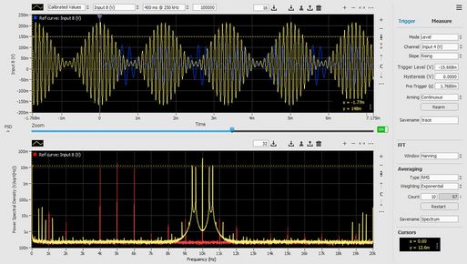
Time-resolved measurements are of key importance when dynamic processes need to be understood. Yet, for processes taking place in µs to ms timeframes, the typical oscilloscopes used for this purpose lack the combination of dynamic range, resolution and noise performance, and due to the lack of integration with data acquisition, triggering can be cumbersome.
The high-resolution oscilloscope and spectrum analyzer module overcome these limitations thanks to the precise and low-noise 18-bit inputs of the SC5 and the tight integration into the Nanonis software. For precise analysis in the frequency domain, the 500’000 points FFT ideally complements the oscilloscope and transforms the module into a full-featured signal analyzer.
- 4 traces with individual scaling
- Up to 1 million points per trace (user selectable), 1 MS/s sampling rate, 100 kHz analog bandwidth
- Measurement time from 32 µs to 17 minutes, variable oversampling up to 1024x
- No need for input range adjustments: 18-bit resolution at 1 MS/s (22-bit at 1 kS/s) and lowest-noise input stage
- No data loss thanks to pre-triggering. Triggering on either analog signals or digital lines is available
- 500’000-point FFT for precise frequency determination and noise analysis
Atom tracking module

The Atom tracking module adds atom tracking capability to the Nanonis base package. It is designed to track topographical features (not only atoms) dynamically and can therefore measure and compensate for thermal drift and sample tilt. A fully automated procedure automatically calculates drift velocity and sample tilt in both X and Y-directions as well as drift in Z-direction and compensates for these. This module is of particular interest when the tip position has to follow a local extremum (e.g. an atom or molecule, maximum or minimum) between point-spectroscopy or when scanning a small scan area where drift is highly noticeable. It can also be used to track diffusion on the surface by activating it and recording the X andY positions as a function of time.
Please head to the Atom tracking product page for more details
Kelvin probe module

The Kelvin probe module is an add-on module to either the OC4.5-Station or the full Nanonis control system (with OC4) and is intended for the mapping of surface charge distribution or contact potential difference (CPD) between tip and sample. Its fully digital implementation allows for maximum flexibility and does not require any additional wiring. Any channel can, for instance, be selected as input signal for either amplitude or frequency shift modulation modes. An internal lock-in demodulates the input signal and a PI-loop regulates the bias voltage to compensate for the change in contact potential. The modulating AC component of the bias voltage, defined by the user, is internally added to the regulated DC bias voltage.
Multi-excitation module for OC4
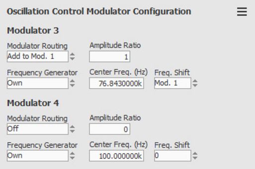
The multi-excitation module adds two additional frequency generators to a single- or dual-OC4 configuration.
The frequency generators can be freely configured:
- The reference frequency can be user-selectable or locked to that of another frequency generator
- The reference phase can be user-selectable, relative to another frequency generator or relative to a demodulator (input signal)
- The amplitude can be user-selectable or a fixed ratio of another amplitude
The module is typically used for exciation schemes where multiple frequencies are used to excite a cantilever, for Q-control, for amplitude modulation and for sideband detection. Dedicated modules provide a step by step configuration for dual-excitation schemes and for sideband tracking
Generic PI-controller modules

The PI controller modules add a flexible control loop to the Nanonis Mimea™ software. They are typically used as additional Z-controllers for multiprobe systems, but they can be used as general feedback modules for adjusting gate voltages in order to keep an input signal at a given setpoint, for adjusting the lock-in amplitude to keep a predetermined potential across a sample, or as temperature controllers.
- Controls on any input or internal signal
- Feedback signal can be applied on any output or internal signal
- If-then mode for two-state control
- DC or AC (lock-in) mode for temperature measurements, for example
- 6 kHz control bandwidth
- Voltage limits for feedback signal
- Up to 8 modules available
Interferometer controller module

For ultra-sensitive detection of cantilever deflections, fiber interferometry is a powerful technique. Nanonis has introduced an active feedback loop to control the gap between the fiber-end and the back surface of the cantilever, ensuring detection of the cantilever motion at the optimal working point of the interferometer signal.
The module performs an automatic calibration of cantilever deflection and piezo movement according to the wavelength of the laser, and automatically adjusts the operating point in order to optimize the sensitivity.
The deflection can be measured either through the interferometer signal (open loop) or by the piezo movement (closed loop).
The module is compatible with a Fabry-Pérot interferometer type.