
Nanonis Oscillation Controller
For the finest control of mechanical oscillators
Highlights
- Fully digital PLL up to 5MHz: no introduction of noise or drift from analog or mixed signals
- Digitally integrated into the Nanonis control system
- Any signal or combination can be used as z-feedback and user-defined SafeTip™ features
- Easy access and analysis of internal signals reporting frequency shift, amplitude, phase and excitation
- 4 independent demodulators for multifrequency operation
- Advanced filtering: independent lock-in filters with selectable order (1 to 8) and cut-off frequency (100 mHz to 50 kHz) for each demodulator
- Integrated oscilloscope and spectrum analyzer (FFT) with continuous display up to 5MHz
- Demodulation bandwidth up to 5 kHz
- Frequency and phase sweep spectrum for maximum amplitude and minimum excitation
- perfectPLL™: automatic PLL-tuning according to the Q-factor, demodulation bandwidth, and gain
- Q-control with arbitrary phase
- TrueDissipation: automatic correction of apparent damping for precise dissipation measurements (requires dual-OC4)
Instrument features
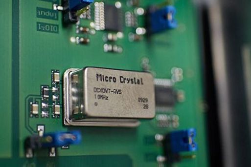
The OC4 hardware is designed to meet the demanding needs of AFM experiments: Low-noise inputs and outputs, a differential input buffer, wide-range variable gain and variable attenuation ensure perfect handling of sensitive signals. Frequency stability of 1ppb is guaranteed by an on board OCXO (oven control quartz oscillator) and frequency resolution down to below 1 nHz through a Direct Digital Synthesizer (DDS) is achieved. The input range of ±10 V ensures that the instrument is compatible with almost any AFM
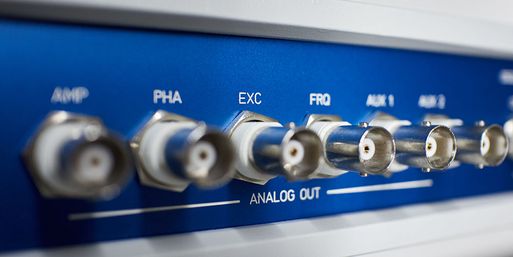
The OC4 interface is intended to work with any third party controller when the OC4 is operated as a standalone PLL (OC4.5-S). All internally calculated channels can be sent out simultaneously over 6 BNC outputs. Two outputs are user configurable for SafeTip signal or Bias voltage for Kelvin probe, for instance. Triggering and synchronization with respect to the drive signal can be done through two trigger ports.
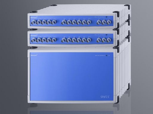
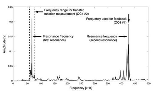
Dual-OC4 for AM-KPFM
While a topographic AFM image is usually acquired with the first resonance frequency of the cantilever, a myriad of additional information such as electrical and mechanical properties of the material can be acquired simultaneously by taking advantage of multiple excitation frequencies.
In contrast to the multi-excitation add-on module, which sums multiple excitation signals into the same physical output, a dual-OC4 system offers two fully independent signal paths, as required for AM-KPFM measurements.
Both the OC4.5-Station and the Nanonis Mimea™ SPM Control System can easily be upgraded to a Dual OC4. The modularity of such a system allows the user to operate each OC4 as either a Lock-in amplifier or a Phase Lock Loop (PLL), independently or in a synchronous manner. A wealth of new dynamic AFM modes become available with many new SPM applications to explore.
The Graphical User Interface integrates a second Oscillation Controller Module leaving the user the freedom to operate either OC4 as a lock-in or a PLL within the same unified interface. The input of each device can be the same, to check first and second flexural modes of the cantilever for instance, or completely independent, to compare two different frequencies. Both lock-ins are synchronized with the same OCXO making them perfectly phase-coherent.
Oscillation controller software
AFM experiments can range from simple intermittent contact imaging to multi-excitation and multi-frequency FM-AFM. The oscillation control software provides the advanced interface required for coping with all of these experimental challenges. It provides a simplified workflow and can be adapted to the complexity of the experiment with a few clicks, guaranteeing that the user only sees what is needed without compromising on functionality.
Under the hood, a set of advanced filters with up to 8th order slope and large cutoff frequency range allows for a precise amplitude and phase determination of the large dynamic range and multispectral signals typical for advanced AFM experiments.
Multifrequency made easy
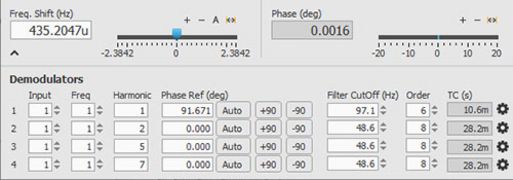
The oscillation control module provides all necessary information for AFM operation with a compact and logical interface. Complex settings, multifrequency and controller configurations are easy to access, but can be hidden thereby allowing for a better focus on the essential parameters. Only a few clicks are required for displaying the full feature set of the module.
The multifrequency functionality is neatly integrated into the workflow of the oscillation controller. Configuration of the 4 independent demodulators is straightforward, and the digital integration of the module in the SPM control system greatly simplifies data acquisition compared to external solutions requiring analog interconnections. A configuration utility helps choosing the best filter slope and time contsant for the lock-in demodulators
Optimized feedback loops: PerfectPLL™
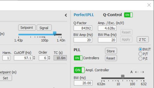
The perfectPLL™ algorithm determines the optimal feedback parameters of both Amplitude and Phase loops based on the Q-factor. This ensures perfect operation of the PLL with no ringing or slow feedback behavior. All relevant parameters are measured and applied automatically in the Frequency Sweep module, leaving the user only with the demodulation bandwidth to choose from a few Hz up to 5kHz (i.e. trade-off between speed & resolution). The phase and amplitude controllers allow on-the-fly adjustments of the demodulation bandwidth for immediate system optimization. Amplitude control can be limited to in-phase control (no active damping) to avoid instabilities in liquids.
Optimized resonance frequency and Q-factor determination
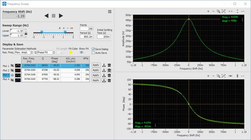
A correct determination of the resonance frequency and of the Q-factor is crucial for an optimal PLL-operation, yet this can be difficult when the signal is very weak or noisy, or when there is high damping (liquids). With the Frequency sweep module this is no longer an issue: The actual resonance frequency can be determined from the amplitude maximum but in case of noisy signals or damping also by fitting the amplitude or phase curves. The same applies to the Q-factor estimation: The Q-factor can be obtained from the phase slope, but also by fitting the phase or amplitude curves.
Q-control built-in
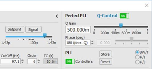
A fast scan speed can be difficult or impossible to achieve with very high Q-factor sensors like the Kolibri sensor or any tuning fork-based sensor. The integrated Q-control tool solves this issue from within oscillation control allowing for a on-the-fly adjustment of the Q-factor.
The Q-factor can be lowered or enhanced, but the choice of an arbitrary phase also allows the compensation of capacitive components in the oscillation signal
TrueDissipation™ (dual-OC4 only)
Dissipation measurements are a powerful tool to determine non-conservative interaction forces, but are often affected by instrument-induced apparent damping. The TrueDissipation™ method removes apparent damping components from measured dissipation data after performing a characterization of the measuring instrument. The calibration procedure runs semi-automatically, and the user is guided through all steps. Both scan and spectroscopy data can be corrected.