HVA4 High voltage amplifier
Low-noise high-voltage amplifier for piezo scanners

The HVA4 family is a set of high voltage amplifiers designed for nano-positioning applications using piezo elements. Three different models with maximum output voltages of ±140 V, ±220 V or ±400 V let the user choose an optimal setup for the required application.
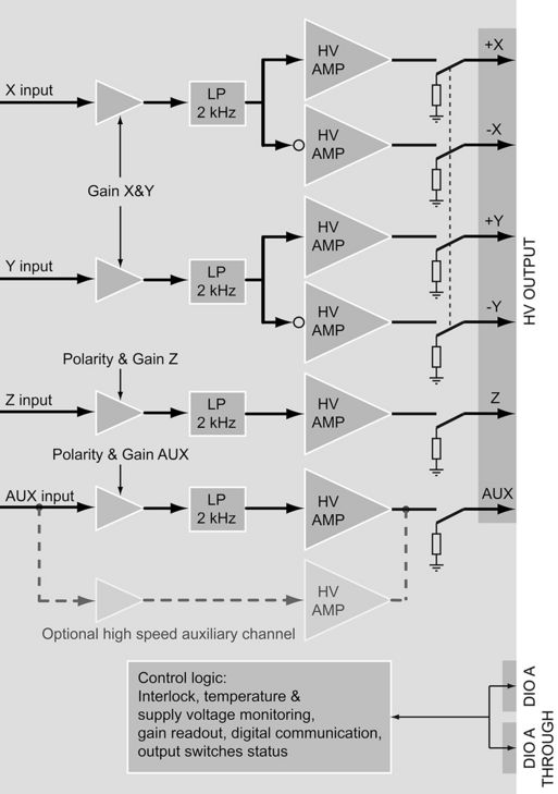
The HVA4 is a six-channel high voltage amplifier featuring four inputs (X, Y, Z and AUX) divided into three groups (X&Y, Z, AUX). Each group has its individual gain selector with 4 settings. Z and AUX inputs additionally have switchable polarities.
With a noise level of only 70μVrms, a noise spectral density below 1 μV/√Hz in a bandwidth of 300kHz and at ±400 V output voltage, the HVA4 offers the lowest noise on the market in scanning probe applications and is ideally suited for low-temperature applications. The HVA4's differential inputs guarantee that the excellent noise figures are not degraded when used in a typical experimental setup. The output of the HVA4 remains absolutely stable even when driving large capacitive loads.
HVA4 versions
The following HVA4 versions are available:
| Name | part number | Maximum output voltage | Gain settings | AUX channel bandwidth |
| HVA4-0214N | 2011751006 | ±140 V | 1, 4, 7, 14 | 2 kHz |
| HVA4-0222N | 2011751007 | ±220 V | 1, 4, 10, 22 | 2 kHz |
| HVA4-0240N | 2011751008 | ±400 V | 1, 4, 15, 40 | 2 kHz |
| HVA4-0222F | 2011751010 | ±220 V | 1, 4, 10, 22 | 1.2 MHz |
| HVA4-0240F | 2011751011 | ±400 V | 1, 4, 15, 40 | 1.2 MHz |
Thermal management
In order to ensure very low drift, the metallic enclosure and an additional aluminum plate of more than 1 kg act as a thermal mass for enhanced thermal stability. The heat generated by high power peaks can easily be absorbed, allowing for a quite fanless design without any moving parts (except for fast AUX channel versions).
Output protection
In order to protect piezos connected to the amplifier the output of the HVA4 is tied to ground with mechanical relays when the amplifier is switched off, or the output is disabled by the user. This effectively protects the amplifier, but also keeps the load connected to ground, when the amplifier is not in use. Piezos are therefore well protected against electrostatic discharge. Further electronic safety measures ensure that the output stage of the HVA4 cannot be damaged by voltage spikes induced by the piezos.
Safety
The HVA4 is short-circuit proof and its temperature and supply voltages are continuously monitored. A thermal shutdown prevents the instrument from exceeding its maximum operating temperature. The high voltage output is protected by an interlock mechanism, which disables all output signals should the output connector be disconnected. Inputs and outputs are all ESD-proof.
Digital interface
The gain settings of the HVA4 and all status information indicated by LEDs on the front panel can be read out over a digital port. The Nanonis software will react accordingly by adjusting calibration values, or by disabling scanning or approach in the event that piezos become disconnected or incorrect settings are applied.
Optional high speed channel for piezo motors
The auxiliary channel can be optionally fitted with a fast amplifier stage (1.2 MHz bandwidth) capable of delivering a peak current of up to 90 mA. Together with the waveform generator of the Nanonis base package, this will turn the HVA4 into a high performance and cost saving fine and coarse positioning solution in a compact package.
Separated high voltage ground
A well thought-out ground concept is of fundamental importance for reducing noise and hum in an experimental setup. Therefore high voltage ground and protection earth are separately available, with no compromise in safety. The scientist can thus adapt the device to the laboratory‘s setup and optimize performance.
Block diagram
SPECIFICATIONS
| Number of outputs | 6 (+X, -X, +Y, -Y, Z, AUX) |
| Number of inputs | 4 (X, Y, Z, AUX) |
| Gain selector | For X/Y, Z and AUX, manual selector, digital read back |
| Gain | Depending on model, 4 selectable values |
| Input connectors | BNC |
| Input coupling | DC, differential |
| Differential input voltage range | ± 10 V |
| Output connectors | Souriau TRIM TRIO UTG01619S |
| Output coupling | DC, referenced to HVGND |
| Voltage range | Up ±400 V for gain 40 |
| Differential input impedance | 1 MΩ @ DC, 100 kΩ @ 2 kHz |
| Bandwidth | 2 kHz, 10 kHz optional, 1.2 MHz for fast AUX channel |
| Maximum output current | 27 mA (90 mA for fast AUX) |
| Output impedance | 200 Ω (100 Ω for fast AUX) |
| Output noise 0.1 Hz - 10 Hz | < 1.5 μV RMS, 8 μV p-p (gain 14, input shorted) < 2.5 μV RMS, 15 μV p-p (gain 22, input shorted) < 5 μV RMS, 30 μV p-p (gain 40, input shorted) |
| Output noise 10 Hz - 300 kHz | < 35 μV RMS, 290 μV p-p (gain 14, input shorted) < 40 μV RMS, 320 μV p-p (gain 22, input shorted) < 65 μV RMS, 510 μV p-p (gain 40, input shorted) |
| Output noise density | < 420 nV/√Hz (@ 300 Hz, gain 14, input shorted) < 550 nV/√Hz (@ 300 Hz, gain 22, input shorted) < 1 μV/√Hz (@ 300 Hz, gain 40, input shorted) |