Mimea Base Package BP5e DISCONTINUED
The Mimea base package BP5e is the latest evolution of the Nanonis SPM control system. It combines exceptional signal quality, high speed and a flexible, powerful and user-friendly software interface. The enhanced BP5e builds on the exceptional performance and signal quality of the BP5 and offers higher speed and more functionality and flexibility.
The BP5e base package provides all the functions for fundamental SPM applications, in particular STM and contact mode AFM. From signal conditioning and AD/DA conversion to FPGA and real-time signal processing and graphical user-interface, the BP5e provides a complete framework that can be adapted and extended with a wide range of add-on modules.
All basic processes such as scan control, spectroscopy, Z-control, fast data acquisition, data monitoring and logging, spectroscopy, atomic manipulation and lithography are included, allowing easy control of most STM and AFM operations. The software provides measurement methods and complete signal processing combined with a modern and easy to use graphical interface, offering all necessary functionalities and an efficient workflow for demanding SPM experiments.
The BP5e can perform scanning and spectroscopy measurements up to 50x faster than with the previous generation. Up to 1,000,000 pixels per second can be generated and directly streamed to disk for up to 8 channels. This makes it possible to acquire extremely highly resolved topography or spectroscopy maps in a significantly shorter time.
With a 64-bit software where memory is no longer a limitation, the only barrier is given by disk space. Spectroscopy is not limited to specific output signals thereby making electrical transport measurements, as an example, much faster and easier to perform. Even time can be a spectroscopy channel, allowing continuous acquisition of raw data at ADC sampling rates.
More details about the BP5e can be found below, on the Mimea main page or in the Brochure (download link at the bottom of this page)
Fully digital system
All analog signals are converted immediately into the digital domain, where all signal processing is performed, making them essentially immune to external noise and crosstalk and ensuring the best possible signal quality, which is crucial for SPM applications. In combination with the powerful software package, signal routing, signal monitoring and any operation between signals can be adapted and optimized on the fly with the press of a button instead of adjusting external hardware cabling.
A fully digital system is also flexible and scalable, since software adaptations are all that is needed for rapid custom developments of the system. Even adding more signal interfaces, should more connectors become necessary, is a plug and play procedure as all corresponding signals become immediately available in the existing user interface.
Plenty of channels
The system handles 128 live signals in real-time: Up to 40 outputs, up to 24 inputs with the remaining signals being user configurable internal signals. Up to 24 signals can be acquired simultaneously with up to 8 additional signals streamed to disk at up to full ADC speed. The base package offers 8 inputs and 8 outputs which allow the connection of signals including bias voltage, current, scan signals, lock-in signals, etc., and any combination of different signals in the digital domain.
The hardware also supports multiple PLLs for AFM operation, thus allowing operation of even the most complex measurement set- ups.
This very large number of live signals can not only be monitored, but also all signals are displayed as real world numbers in floating-point representation, with assigned SI units for immediate quantitative results, without the need of additional calibrations during data analysis.
Signal analysis and monitoring
All signals can be inspected with the FFT spectrum analyzer, dual-channel oscilloscope, signal charts, and history panels. Such fully digital and integrated software instruments are much more efficient in use, less invasive, better in performance, and lower in cost than their external counterparts.
The ability to digitally route live signals to software instruments during active measurements without any negative impact on signal quality is truly invaluable when optimizing the experimental set-up, eliminating disturbances and thus improving the quality of scientific results.
High resolution AD/DA conversion
The signal frontend of the Base Package, the Nanonis SC5, uses the latest advances in AD/DA conversion technology, in combination with sophisticated digital filtering, oversampling, and dithering techniques, to provide the highest resolution.
All outputs of the SC5 and SO5 use 20-bit resolution DACs with 1-ppm precision, the best available on the market. just a few years ago, similar performance on multiple outputs would have been impossible to realize. The patented hrDAC™ technology turns these state-of-the-art converters into real 22-bit devices, which in a traditional approach would fill a rack with single-channel instruments and cost ten times as much.
Measurements requiring very small modulations with large offsets are thus possible without the need for drift- and error-inducing analog circuits or external mixers or attenuators. The impressive dynamic range also eliminates the need for switching gains, therefore coordinates are absolute over the full signal and scan range.
Lowest noise and drift
When experiments involve energies of a few μeV, high resolution alone is not the only pre- requisite for a measurement interface: Low noise is of utmost importance, and the SC5 delivers impressive performance on both inputs and outputs. The noise floor of the SC5 and SO5 lies below 25 nV/√Hz with an output voltage range of ±10 V. Despite its large bandwidth of 40 kHz, the output noise does not exceed 10 μV RMS at a measurement bandwidth of 300 kHz, meaning that the noise contribution of the SC5 is irrelevant in experimental situations.
Scanning probe microscopes require very stable signals over long measurement times. For this reason, the SC5 and SO5 are equipped with a custom temperature-stabilized, high precision voltage reference. The reference has a very low inherent noise and drift. Temperature stabilization combined with thermal decouplingallows reduction of the temperature coefficient to below 3 μV/°C and output drift to below 1.5 μV in 12 hours at 0 V.
In contrast to broadband noise, which can be easily filtered, 1/f noise cannot be eliminated and becomes an issue for experiments requiring signals to be very stable. The outputs of the SC5 and SO5 have been designed keeping this in mind, leading to a noise level below 750 nV peak- peak (0.1 – 10 Hz, ±10 V range), or about 223 times smaller than the maximum output signal.
Optimal SNR for small signals
A custom-designed input stage allows acquisition of the weakest analog signals, without compromises in dynamic range. The signals are digitized at an early stage with 18-bit AD converters running at 1 MS/s and then processed in the digital domain. Adaptive over- sampling is used to always obtain the best signal-to-noise ratio for a given data acquisition rate. The user does not need to care about adjusting time constants, as the data acquisition automatically provides the best setting.
For even smaller signals, for direct measurements of high-resistance samples, for true differential measurements or simply for extremely small signals, the newly developed MCVA5 voltage amplifier is the ideal frontend to the SC5. It provides staggering 10 TΩ input impedance (to GND), an input spectral noise below 4 nV/√Hz (single-ended at 1 kHz and gain 100), over 120 dB of common-mode rejection and over 500 kHz bandwidth at any gain setting. Remote control is provided for gain (1, 10, 100, 1000), coupling (DC, AC) and input mode (A, A-B).
The preamplifier is seamlessly integrated into the Nanonis software meaning that all calibrations are automatically adjusted when the gain is switched. The design ensures exceptional low-frequency performance resulting in a noise density below 11 nV/√Hz at 1 Hz and 0.1-10 Hz noise of only 25 nV rms (gain 100, single-ended).
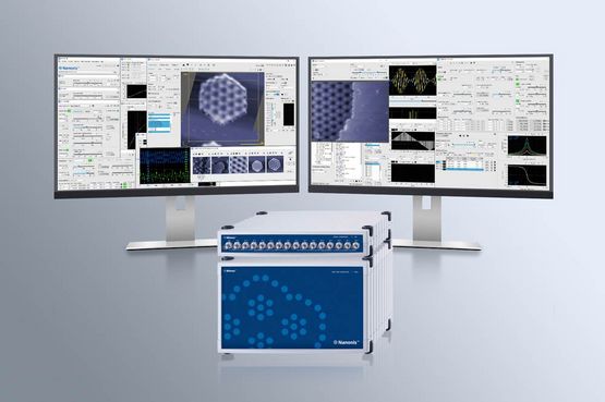
Nanonis Software: the most advanced user interface for SPM
The user interface, or in aeronautical terms the cockpit, is the crucial part of the measurement system when recording of high quality data in a short time is required. The growing complexity of modern SPM experiments requires control of a large number of parameters.
To ensure that the user is not overwhelmed by the resulting experimental complexity, the user interface is designed based on the typical workflow of SPM measurements, with all functions accessible but with the option to only display the relevant ones. A streamlined design ensures that the software is easy to use and that even inexperienced users can work more productively and safely.
More details about the software can be found in the Mimea software page or in the brochure (download link at the bottom of this page)
Expansion
The BP5e provides plenty of synchronization options through its digital ports: 32 bidirectional digital lines on 4 independent ports give sufficient flexibility for read-out and control of both Nanonis and external instruments. High-speed triggering is available through four 200 MHz high-speed digital lines. For high speed counting applications, four dedicated lines allow counting rates of up to 100 Mc/s.
The modularity of the Nanonis Mimea SPM control system means that the hardware required for a given experimental situation can be tailored to the user’s needs. This is the most flexible and at the same time cost-effective solution, and offers the best performance since each instrument is highly optimized. Hardware add-ons include the Oscillation Controller, high-voltage ampli-fiers, piezo drivers, and adaptation kits for commercial microscopes.
Modularity doesn't stop at the hardware level: The modularity of the software is a key advantage in cost optimization. Additional software modules can be added when experimental needs require them. The addition of new modules does not require any hardware or software installation, and can be performed in a very short time.
Please head to the Mimea add-ons page for more information about hardware and software add-ons.
Customization
Competitive advantage in research is often based on the modification of an instrument that allows the researcher to perform experiments in a way nobody else has done before. This is where the Programming Interface steps in: to give you the building blocks to design your own experiment. The user can either program in LabVIEW or in Python, Matlab, C++ or any other programming language able to write to and read from a TCP port on the host PC.
The LabVIEW Programming Interface consists of libraries to access the controls and functions of the graphical user interface. It is used to automate experiments, sequences, calibration routines and experimental procedures. Polling of parameters and signals at high rates allows for supervision and alarm settings, and many other features. With the LabVIEW interface the Nanonis SPM Control System provides full access to all the features provided with LabVIEW: graphs, database access, convenient data handling, TCP/ IP, GPIB, RS232, USB access to other instruments, signal analysis functions and much more.
The generic TCP interface offers all functionality of the LabVIEW interface but with the commands sent to and received from a TCP port of the Nanonis software on the host PC in a generic script format. It lacks the ease of use and debugging options of LabVIEW, but is not bound to a specific programming language and grants a simple integration of the SPM Control System if existing software routines are not available in LabVIEW.
For experiments where exact timing is crucial, the scripting module becomes the ideal tool for customization: Scripts are executed on the real- time system in a time-deterministic manner, improving the time response by a factor of 100 compared to the programming interface. Logic functions can be implemented with the use of FOR loops and IF conditions. Triggering over TTL lines directly from the real-time system is ideal for fast synchronization and optical experiments.
Scripting is fully integrated into the spectroscopy options of scan control and is ideally suited for time consuming measurements like Kelvin Probe and multipass techniques, reducing dwell times and improving measurement precision. It can also be combined with the Programming Interface offering the best of both worlds: speed andflexibility.
SPECIFICATIONS
| Operating temperature | +5° C to +35° C |
| Power Supply | RC5e: Built-in universal power supply, max. 220 W |
| Power Supply | SC5: Built-in linearly regulated power supply, toroidal transformer, automatic line voltage detection. Max. 51 W |
| Power Input | RC5e: 100 – 230 V, 50 - 60 Hz |
| Power Input | SC5: 100 – 240 V, 50 - 60 Hz |
| Real-time system | NI PxIe-8840 real-time system with Intel Corei5 CPU 2.7 GHz, 4 GB RAM |
| Operating system | NI LabVIEW Real-Time OS |
| FPGA card | NI PXIe-7976 |
| Connectivity | 3x SC5 max., 2x SO5 max., 2x OC4 max. Total of max. 6 frontends |
| Electrical GND | 10 kΩ AGND to chassis, decoupled from RC5e |
| Data transfer | Via TCP/IP, 2 kS/s default, up to 20 kS/s, 1 MS/s x 8 channels for data streaming |
| Analog inputs | If not otherwise specified, all specifications for ±10 V input range |
| Number of Connectors | 8x BNC connector, differential |
| Differential input voltage range | ± 10 V |
| Differential input voltage range | ±10 V, ±1 V, ±100 mV, ±10 mV (with MCVA5) |
| Analog bandwidth | DC – 100 kHz (-3 dB), 5th-order Butterworth low-pass filter |
| Differential input impedance | 2 MΩ |
| Input impedance | >10 TΩ to GND, >50 GΩ differential (with MCVA5) |
| Input bias current | <2 pA typ. (with MCVA5) |
| AD-converter | 18-bit, no missing codes, 1 MS/s |
| Effective resolution | 20-bit @ 60 kS/s, 22-bit @ 1 kS/s (oversampling) |
| INL | ±2 LSB typical |
| DNL | ±1 LSB typical |
| Input noise density | < 150 nV/√Hz @ 10 kHz, < 650 nV/√Hz @ 10 Hz |
| Input noise density | <4 nV/√Hz (<5.5 nV/√Hz) @10 kHz SE (differential) |
| Input measurement noise | < 100 μVrms @ 1 MS/s, < 25 μVrms @ 60 kS/s, < 6.5 μVrms @ 240 S/s |
| 0.1 Hz - 10 Hz noise at gain 100 | <25 nVrms (< 32 nVrms) SE (differential) |
| 12 h drift | < 80 μV (< 100 μV) @ 0 V (@ 9.9 V) |
| THD+N | > 120 dB @ 100 Hz, > 95 dB @ 1 kHz, |
| CMRR | >125 dB @ 10 Hz >120 dB @ 100 Hz >100 dB @ 1 kHz (with MCVA5 @ gain 100) |
| Analog outputs | all specifications for ±10 V output range |
| Number of Connectors | 8 x BNC connectors (SO5: 16x BNC connectors), referenced to AGND |
| Output voltage range | ±10 V into 1 kΩ or larger |
| Output impedance | <1 Ω, short circuit safe |
| Analog bandwidth | DC – 40 kHz (-3 dB), |
| DA-converter | 20-bit, 1-ppm precision, 1 MS/s |
| Effective resolution | 22-bit, patented hrDACTM technology with active glitch compensation |
| INL | < ±2 LSB max. < ±1 LSB typical |
| DNL | < ±1 LSB max. < 0.5 LSB typical |
| Output noise 0.1 Hz - 10 Hz | < 200 nVrms (0.1 – 10 Hz) |
| Output noise density | < 25 nV/√Hz @ 100 Hz, < 75 nV/√Hz @ 1 Hz |
| Output noise 10 Hz - 300 kHz | < 10 μVrms (10 Hz – 300 kHz) |
| 12 h drift | < 1.5 μV (< 25 μV) @ 0 V (@ 9.9 V) |
| THD+N | > 93 dB @ 100 Hz, > 93 dB @ 1 kHz, > 79 dB @ 10 kHz (9V output signal) |
| Digital lines |
|
| Number of Connectors | 4 x 8 bidirectional lines on four D-sub 9 female connectors |
| Signal | 3.3 V TTL, max. 25 mA per line |
| Maximum sampling frequency | 500 kHz |
| High-speed digital lines |
|
| Number of Connectors | 4 x inputs and 4 x outputs on SMB male connectors |
| Signal | 3.3 V TTL, max. 33 mA per line |
| Maximum sampling frequency | 200 MHz |
| Clock |
|
| Number of Connectors | 1 x input, 1 x output for active clock source on SMB male connectors |
| Frequency | 10 MHz, square wave, 3.3 V |
| Accuracy | ± 50 ppm (standard clock), ± 4 ppm (optional OCXO) |
| Dimensions | 32.5 x 28 x 21 cm (RC5e) |
| Dimensions | 32.5 x 28 x 7 cm (SC5) |
| Weight | 8 kg (RC5e) |
| Weight | 4.2 kg (SC5) |